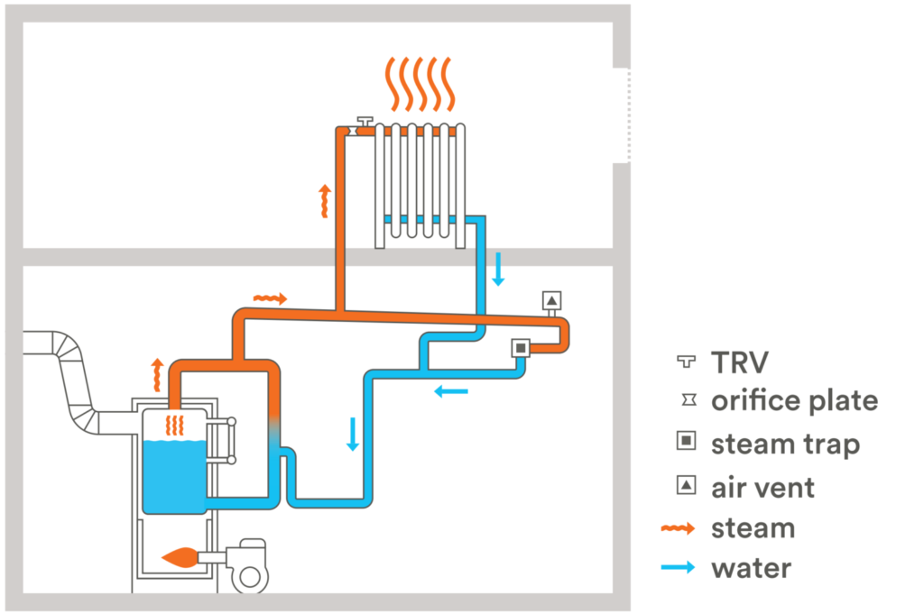
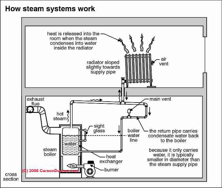
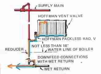
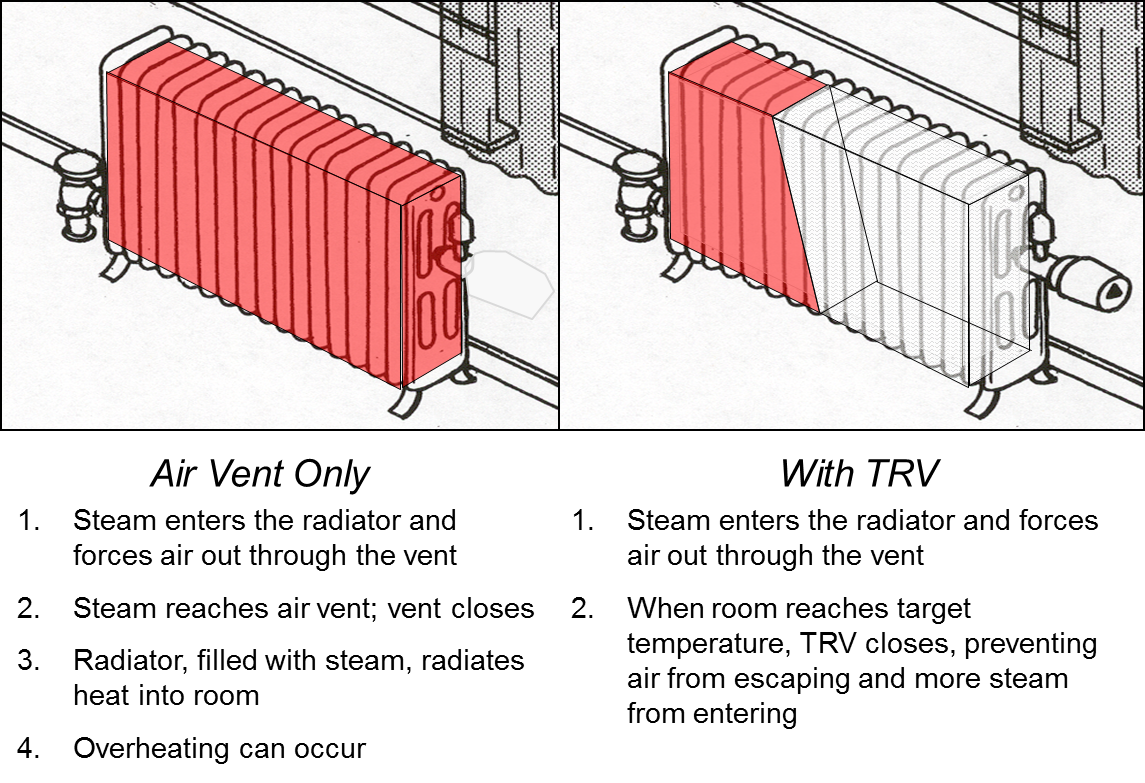
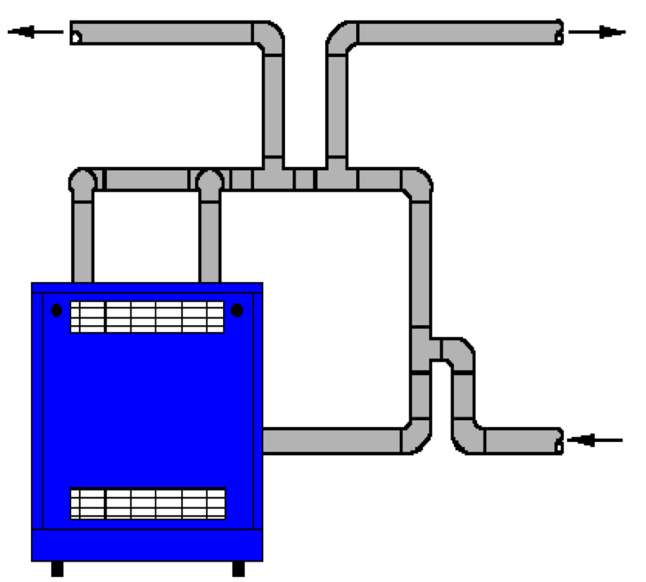
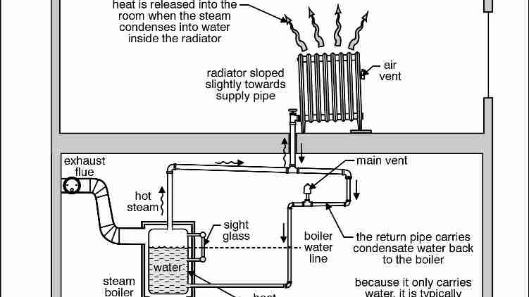
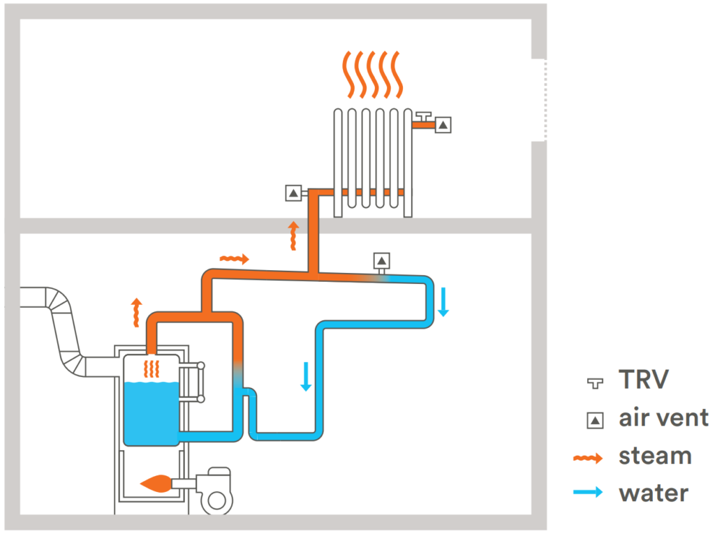
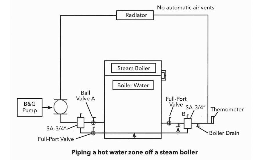
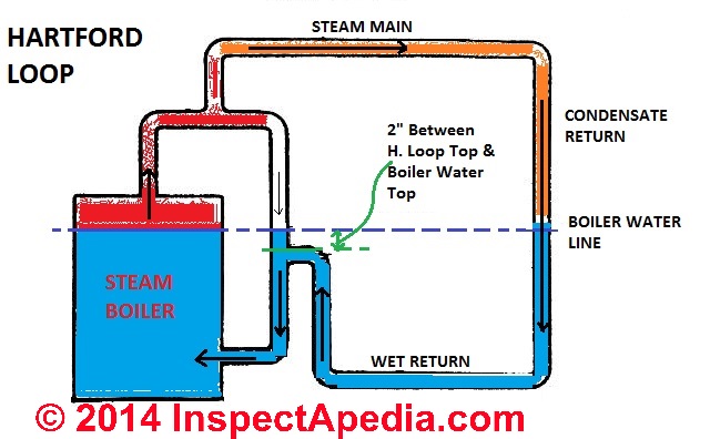
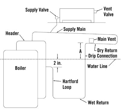
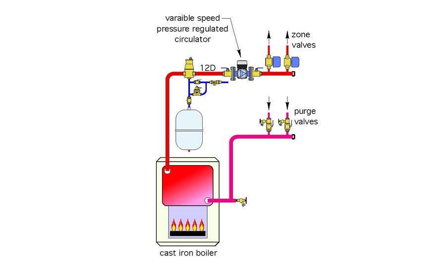
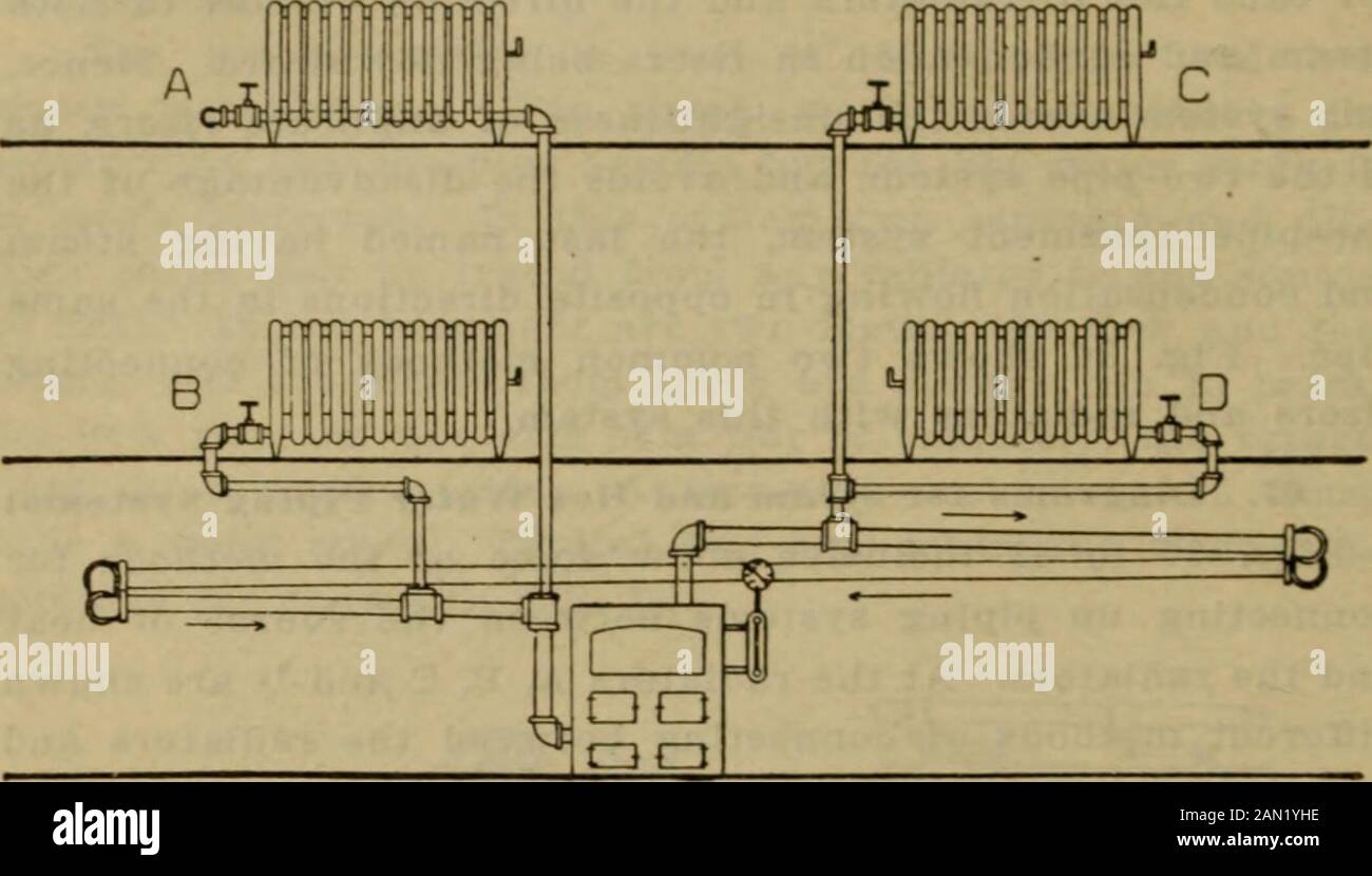
Two Pipe Steam System Diagram
Two pipe steam system diagram. 12713 Process Flow Diagram. This made the steam inside it condense creating a partial vacuum and atmospheric pressure pushed. Figure 54a shows the phase diagram of Ethane-normal Heptane system.
Typical P-T Diagram for a Multi-component System. Vapour Power Cycle T. Minor Dynamic Loss Coefficients for Pipe or Tube System Components - Minor loss coefficients for commonly used components in pipe and tube systems.
This type of tubing has high mechanical performance high corrosion resistance high. Carbon steel pipe is used as the base pipe of bimetallic combination tubing which has an internal liner made of stainless steel titanium alloy steel copper or aluminum and so on. Since the energy can be transformed between two mediums or transferred into other forms of energy a thermal engineer must have knowledge of thermodynamics and the process to convert generated energy from thermal sources into chemical mechanical or electrical.
As it shows the critical temperature of different mixtures lies between the critical temperatures of the two pure components. 1 Hilti KB-TZ2 may be directly substituted for TZ in this detail. The circulating cooling water performs the extraction of the heat from the steam.
CS is a control surface that separates control volume from the surrounding. Uncondensed gases consisting of NH 3 CO 2 H 2 O and inerts rising from the bottom are absorbed by cold liquid NH 3 reflux in the upper section of the column. Bijan Elahi in Safety Risk Management for Medical Devices 2018.
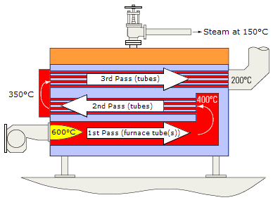
Schematic diagram of parallel and counter flow steam condensers. The process flow diagram is divided into three sections. Superheating the steam to higher temperatures has very desirable effect.
Partially condensed NH 3 -CO 2-H 2 O mixture from MP. A PFD helps with the brainstorming and communication of the process design.
Carbon steel pipe is used as the base pipe of bimetallic combination tubing which has an internal liner made of stainless steel titanium alloy steel copper or aluminum and so on.
Category III piping systems operate with positive vent pressure and are sealed by the high temperature seals and locking devices built into the Category III approved vent pipe. Other fluids like organics glycols etc. Condenser enters the bottom of the column where it is distributed is carbamate solution by means of sparger pipe distributor. By superheating state 3 will move to the right and up in the diagram and hence produce a drier steam after expansion. The saturated water at the bottom of the steam drum flows down through the down comer pipe normally unheated to headers and water drum. This type of tubing has high mechanical performance high corrosion resistance high. Look at this sketch here a red blue arrow shows that mass energy respectively can transfer to the system and from the system. The critical pressure however exceeds the values of both components as pure in. Nova venting products are single wall and require 6 clearance from combustible material.
The Main Reciprocating Engines. In Steam tracing Fig. Sterilization and to establish sufficient data to assure that the STEAM STERILIZER Equipment ID No supplied by Ms XYZ is suitable for sterilizing planned load. Superheating the steam to higher temperatures has very desirable effect. The critical pressure however exceeds the values of both components as pure in. 12713 Process Flow Diagram. Process topology stream information and equipment information.










Post a Comment for "Two Pipe Steam System Diagram"